Design Tips
Terminology
Angle of attack – Refers to the angle at which the foil meets the flow of water. In the case of rudders, this angle changes as the helm is steered.
Aspect ratio – The ratio of the length to the width of the planform of a rudder or centreboard. High aspect ratio foils are long and narrow, while low aspect ratio foils are shorter and wider. Vessels designed for higher speeds often benefit from high aspect ratio foils, such as those seen on sailboards. Slower boats typically use lower aspect ratio designs.
Chord – The distance between the leading edge and trailing edge of a foil.
Ellipse – A stretched circle or oval. This shape is important in planform design for improving lift and reducing drag.
Foil section – The cross-sectional shape of a rudder or centreboard, similar to an aircraft wing (airfoil), but typically symmetrical for marine use.
NACA 4-digit series (e.g., NACA0008, NACA0010) – A commonly used classification of foil shapes in marine design. The first two digits ('00') indicate symmetry, and the last two digits define the maximum thickness of the foil as a percentage of the chord length. For example, a NACA0008 foil has a thickness equal to 8% of its chord, with maximum thickness located 30% back from the leading edge.
Planform – The outline of the rudder or centreboard when viewed from the side.
Spline – A smooth, curved line defined by several control points. In design terms, it resembles a flexible batten or thin wood strip bent around anchor points. Several mathematical variations exist, each with specific benefits.
Planform
When designing a planform, it must comply with the class rules of the fleet. Some classes allow complete freedom, while others have strict dimensional tolerances.
The simplest planform is a rectangle. It performs well and is easy to manufacture. Performance can be improved by incorporating an elliptical tip, which can be achieved through either an elliptical leading or trailing edge. Full elliptical tips are also possible. These shapes reduce drag and improve lift by encouraging water to flow more efficiently across the foil rather than around the tip.
If a choice is needed between an elliptical leading edge and a straight trailing edge versus a straight leading edge with an elliptical trailing edge, the former provides greater mechanical strength. This may not be an issue if the composite layup is strong enough.
Elliptical foils tend to stall all at once, while foils with squared tips stall at the tip first. In that case, a skilled helmsman may feel the flutter and make corrections in time.
While planform shape contributes significantly to performance, what truly matters is the distribution of pressure across the foil. An elliptical distribution of pressure can often be achieved without a fully elliptical planform.
Rudders
Thickness
Rudder sections are typically thicker, proportionally, than centreboard sections. This is because rudders experience variable angles of attack as the boat is steered, while centreboards move consistently with the hull.
Tradeoffs include:
Thinner foils produce less drag, but also less lift and a lower stall angle.
Thicker foils provide more lift, stall at higher angles of attack, and offer greater structural strength.
For aggressive steering in waves, a thicker foil section is recommended. A NACA0012 section, which is 12% as thick as its chord, is often used as a balanced choice.
Some designers thin the cross-section of the rudder at the waterline to reduce drag. While this improves efficiency, it can also compromise structural strength, particularly in high-stress areas.
Planform
The rudder should offer enough underwater surface area to maintain stability and control. When redesigning a rudder, it is generally best to maintain the same surface area as the original, even if the shape is changed. If surface area data is unavailable, a rule of thumb is that the rudder should be approximately one-third the size of the centreboard.
Higher aspect ratio rudders are more effective at high speeds, offering better feel and control. However, they may become less responsive in light winds. These rudders must also be built stronger, as their longer blades are subject to increased leverage and potential breakage, often near the headstock.
A balanced rudder has a leading edge that extends forward of the pivot point, which reduces the effort needed to steer. This design is common on keelboats and can also be used on dinghies.
Centreboards
Thickness
Centreboards typically operate at low angles of attack, generally equal to the boat's leeway angle (around 3 degrees). This allows designers to use thinner foil sections for reduced drag, without the risk of stalling. The NACA0008 section, which has an 8% thickness-to-chord ratio, is a common choice.
Tapering
Some builders taper the thickness of centreboards to maintain consistent relative thickness as the chord narrows toward the tip. This preserves an ideal foil section throughout the board. Others choose not to taper in order to retain strength, especially if the board is made from solid wood without additional reinforcement.
If the layup over the core is strong enough, tapering is generally preferred. However, if building with unreinforced wood, it is safer to leave the board untapered for mechanical integrity.
In cases where class rules limit the maximum centreboard slot width, designers may not be able to achieve the desired foil section at the hull exit point. In this case, the board should maintain maximum allowed thickness until enough chord length exists to taper toward the ideal section.
Stiffness
An overly stiff centreboard can actually limit performance. When a gust hits the sails, a well-rigged boat responds with mast bend and controlled heel, allowing it to accelerate rather than slide. A centreboard that flexes slightly can contribute to this performance by reducing heel and increasing forward motion.
Competitive sailors often choose centreboard stiffness based on crew weight and sail power. For example, racing sailboarders frequently match their fin flexibility to sailing style and body weight.

Gybing Heads
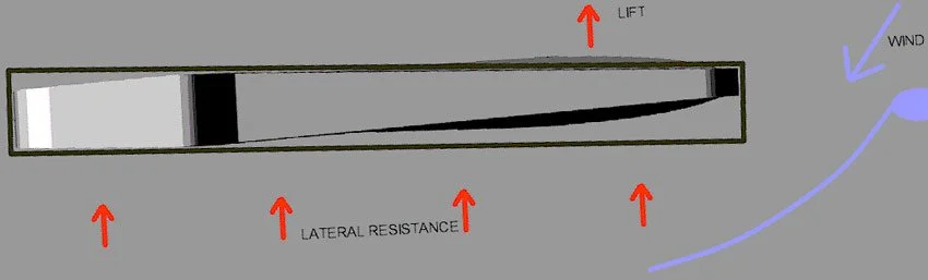
Some boats are designed with gybing head centreboards. In these designs, the board head has a trapezoidal cross-section, which allows the board to pivot slightly within the trunk. This pivoting is caused by the lift force generated by the foil and the lateral resistance acting against the hull.
If the pivot point is located more than halfway back from the leading edge, the forces will press the board against one side of the trunk, causing it to gybe into a fixed angle — typically around 3 degrees. This gybing only occurs when the board is fully deployed. Once raked, the leading edge contacts the trunk and locks the board in place.
The advantage of a gybing centreboard is an increase in the angle of attack relative to the hull’s centreline, which generates additional lift. This allows for a fuller jib and more downwind power while maintaining the same leeway angle. However, not all classes permit gybing boards, and opinions on their effectiveness vary. Some experts, such as Frank Bethwaite in High Performance Sailing, argue that disrupted flow from a gybing board may negatively affect rudder performance.