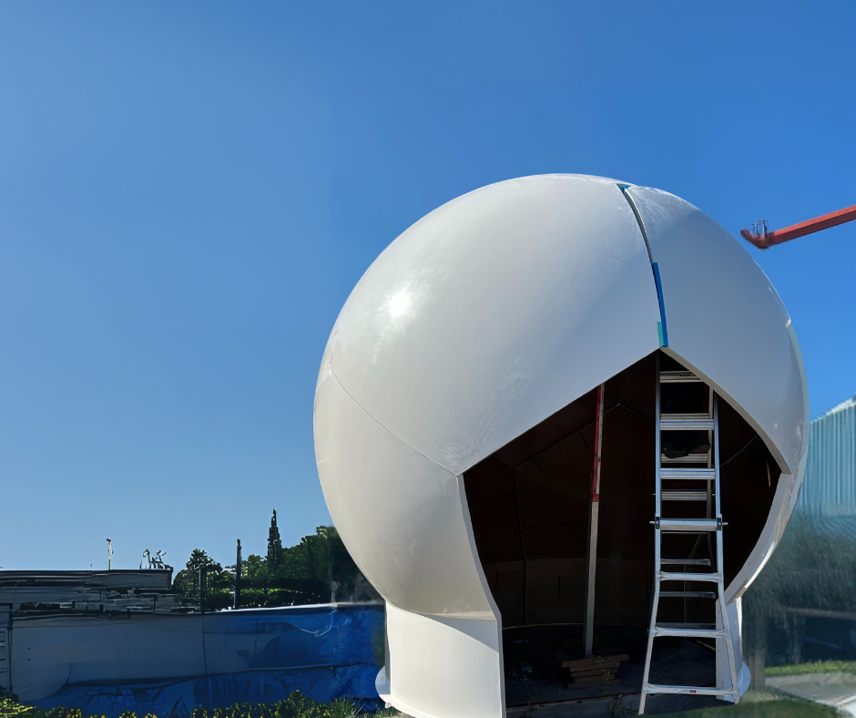
Satellite ground stations are significant investments. The dish, the electronics, the site infrastructure — all of it is built around the assumption that the link to the satellite will be reliable. Weather is one of the primary threats to that reliability, and a radome is how you take it off the table. But not every radome does that job equally well, and the difference comes down to how it was engineered for the specific system it is protecting.
CCI attended Satellite 2026 earlier this year, and the conversations we had there reinforced something we see consistently: satcom operators and ground station integrators understand the need for environmental protection, but the technical requirements of the radome itself are often underspecified until late in the project. This post is an attempt to lay out what those requirements are and why they matter early in the design process.
The satcom environment is demanding
Satellite ground stations are often located based on line-of-sight requirements rather than environmental convenience. That means exposed hilltops, coastal sites, arctic installations, desert facilities — locations chosen for their RF characteristics, not their weather. A radome protecting a satcom antenna at a high-latitude site may face sustained winds, significant ice loading, and temperature swings of 60 degrees Celsius or more across the course of a year.
At the same time, the antenna inside is doing precision work. Satellite communications at Ku, Ka, or higher frequency bands require pointing accuracy measured in fractions of a degree. Any structural deformation of the radome under load that transfers to the antenna mount, or any material behaviour that affects the beam, will show up in link performance.
Frequency band determines the design
The frequency band the antenna operates on is the starting point for any satcom radome design. Ku-band, Ka-band, Q/V-band, and X-band systems all interact differently with composite materials, and the laminate schedule — the layered construction of the radome wall — has to be optimized for the specific frequencies in use.
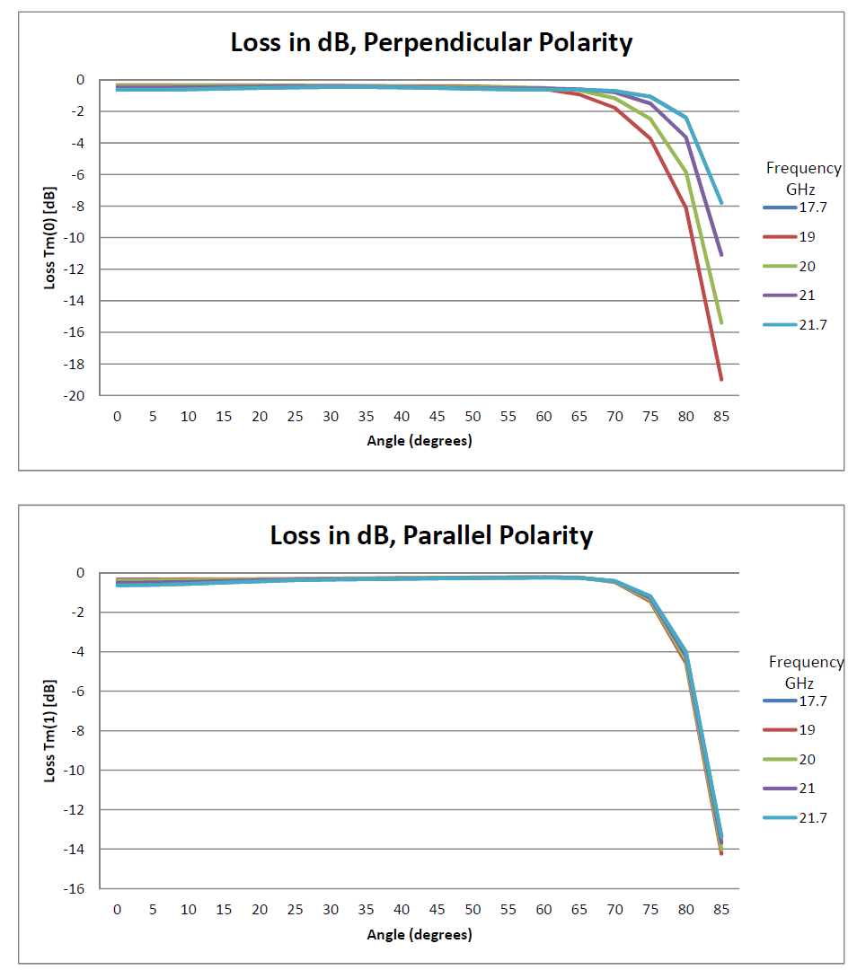
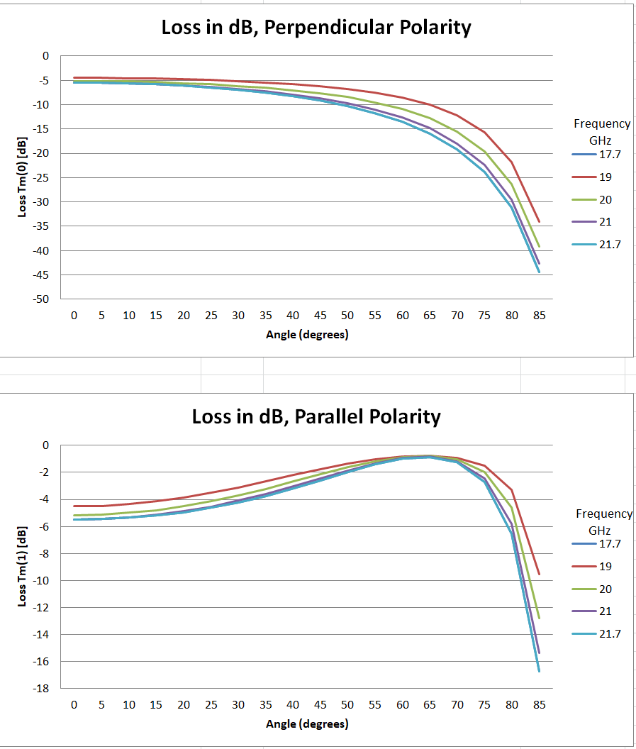
Higher frequency bands are more sensitive to laminate variation. At Ka-band and above, small differences in wall thickness, material density, or layup consistency can produce measurable insertion loss or reflections. This is why a radome built to a general specification and tested at a mid-range frequency cannot simply be assumed to perform at the upper end of the Ka-band or into Q/V territory. The engineering has to track the actual operating frequencies of the system.
Key design variables for satellite communications radomes
Operating frequency band — Ku, Ka, X, Q/V — drives laminate schedule and wall thickness
Antenna aperture size determines radome geometry and structural span requirements
Site environmental loads: wind speed, ice accumulation, temperature range, UV exposure
Pointing accuracy requirements and their interaction with structural deflection under load
Rain attenuation at higher frequency bands and hydrophobic surface treatment options
— Access requirements for antenna maintenance within the radome structure
Rain fade and surface performance
At higher frequency bands, rain attenuation is a real factor. Water on the radome surface can contribute to signal loss, particularly at Ka-band and above, where the wavelength is short enough to interact meaningfully with a water film. Hydrophobic surface treatments and drainage geometry are part of how radome designers address this, and they are worth specifying explicitly rather than leaving as an afterthought.
The same applies to ice. An ice-coated radome surface changes the effective electrical properties of the wall. In regions where icing is a routine occurrence, the radome design should account for it — either through geometry that sheds ice, materials that limit adhesion, or an explicit understanding of the performance envelope when ice is present.
Fixed versus transportable ground stations
The design priorities shift depending on whether the ground station is a permanent fixture or a transportable system. Fixed installations prioritize long-term durability, minimal maintenance access requirements, and performance consistency over the full service life of the antenna. Transportable systems add weight and pack-size constraints, and the radome structure has to survive repeated assembly and disassembly cycles without degradation.
CCI has experience with both configurations. The engineering approach is similar — start from the antenna specifications and the operating environment — but the structural design and material choices reflect the different operational demands of each application type.
When to bring the radome into the design process
The short answer is early. Radome geometry is constrained by the antenna aperture and the required look angles. The structural design is constrained by the site loads and the foundation or mounting system. The laminate schedule is constrained by the frequency bands and link budget. All of those constraints interact, and discovering a conflict late in the project — after the foundation is poured or the antenna is on order — is an expensive problem.
Bringing the radome engineer into the conversation at the site selection or early system design phase gives the project the best chance of a clean integration. CCI is set up to engage at that stage, and we are happy to work through preliminary requirements with operators and integrators before the program has fully defined its specifications.
Next month we’re making the case for Canadian-made radomes — looking at the supply chain and procurement landscape and why CCI is well-positioned to serve defence and commercial programs across Canada and internationally.